Papa Vespa's blog is een blog over het restaureren van een smallframe Vespa en veel meer.


Papa Vespa's blog is a blog about the restoration of a smallframe Vespa and much more.

The best of ... the overhaul - Thanks a million to Luc Pollet for making the compilation.

Harley versus Vespa

Totaal bezoekers sinds maart 2011


woensdag 19 oktober 2011

Hoe een contactslot verwijderen? How to disassemble the ignition switch?

De verdere ontmanteling van het chassis bracht me aan het puntje: contactslot. Blijkt voor sommige een lastig karweitje. Daarom wil ik in enkele stappen en met wat foto's laten zien hoe een contactslot éénvoudig te verwijderen is.


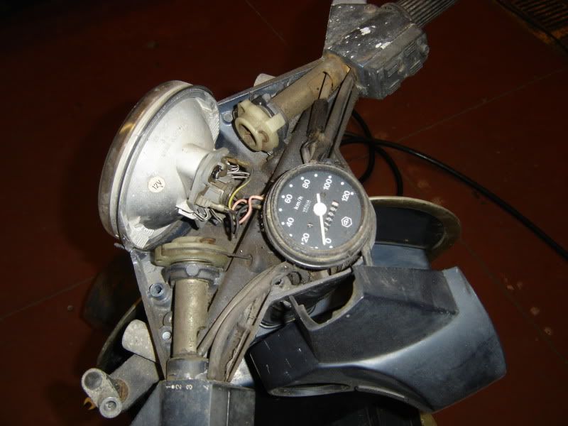
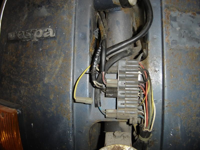
The further dismantling of the chassis brings me to the next  tip: the ignition switch. For some a tricky thing to disassemble. That's why I would like to show you in a few steps with some pictures how simple it is to remove the switch.


Achteraan klikken we het elektrisch gedeelte los van het contactslot. Dit doen we met een kleine platte schroevendraaier door de inkepingen in te duwen en zo het gedeelte los te klikken.


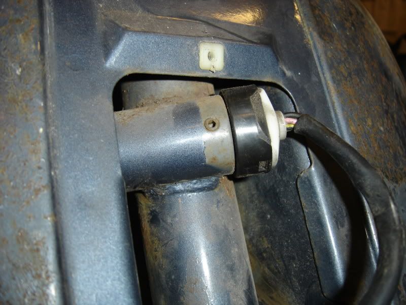
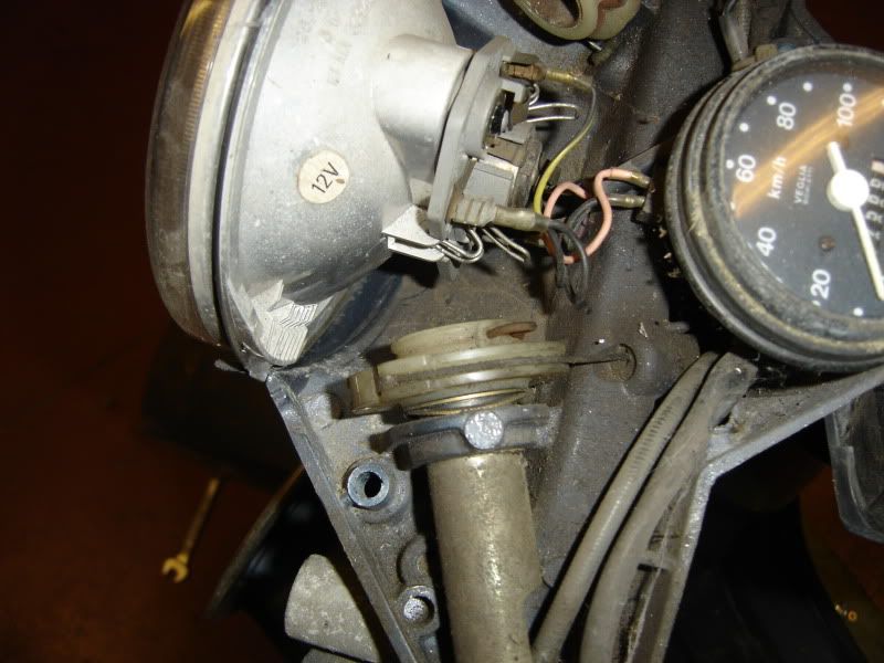
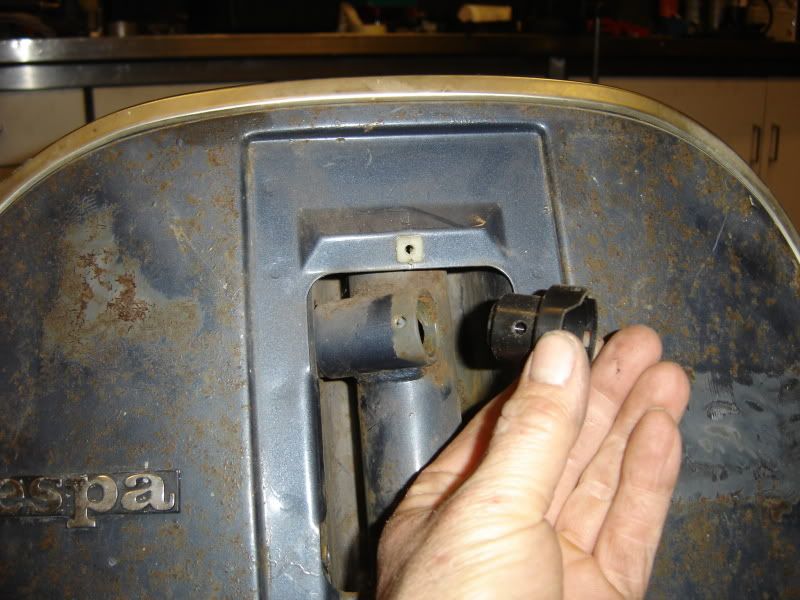
At the back we click off the electrical piece of the ignition. We do this with a small flat screwdriver and push through the notches in the area and thus release the button.


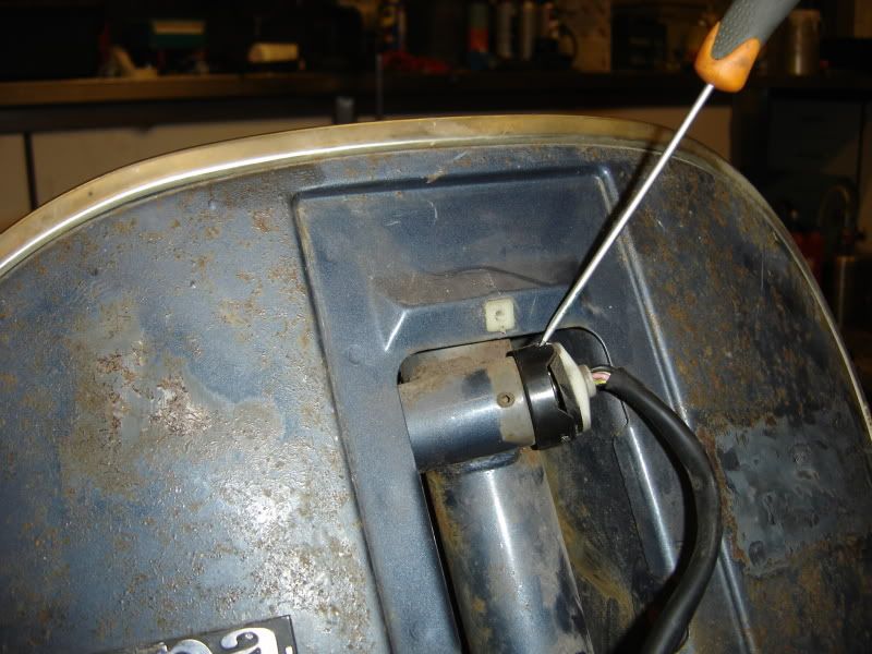
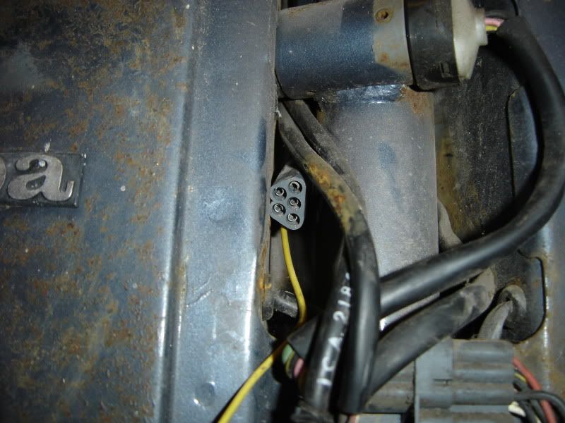
Nu kan je dit gedeelte met bedrading en al verwijderen. Hierna komt nog een gedeelte die we door middel van een imbus vijsje op de zijkant van het contact los draaien om zo ook te kunnen verwijderen.


Now you can remove  the part with all the wiring. Next comes a section that we remove by unscrewing an allen screw on the side .


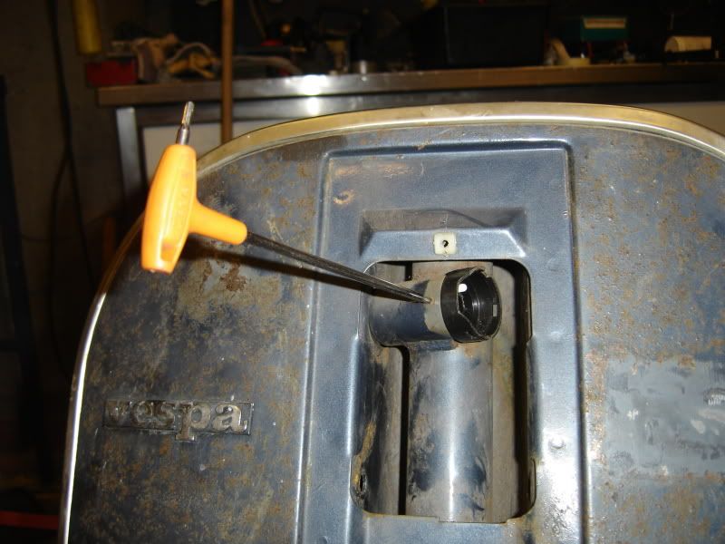
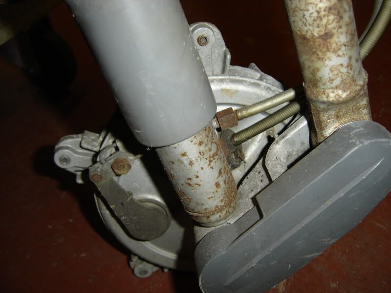
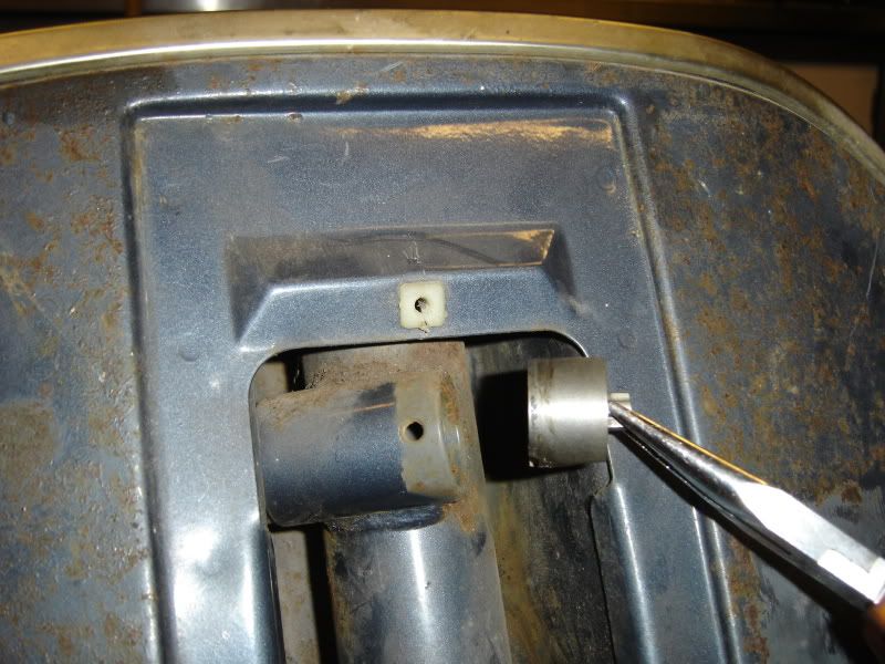
Na deze handeling komt het plastiek gedeelte los om te verwijderen.

After this operation you can remove the plastic part.


Het volgende is nog een metalen stuk die gewoon los zit en zo uitgehaald kan worden met een puntbek tang.

The following is a piece of metal that is loose and can be removed with a forceps.


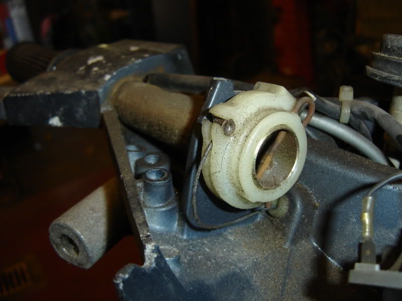
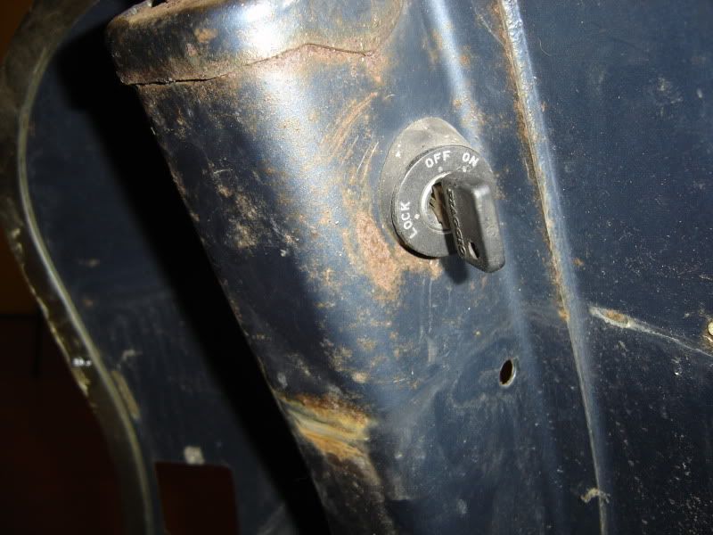
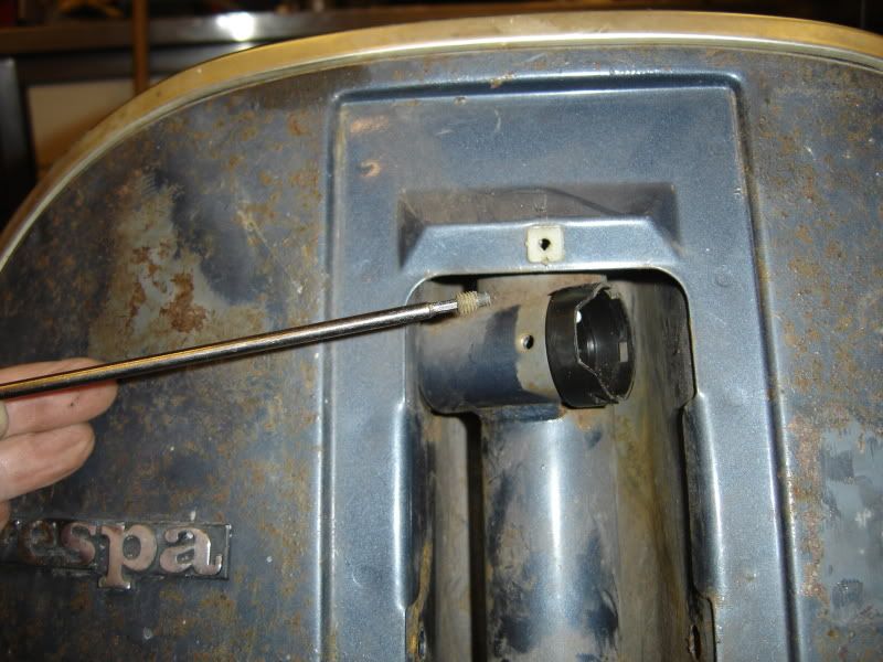
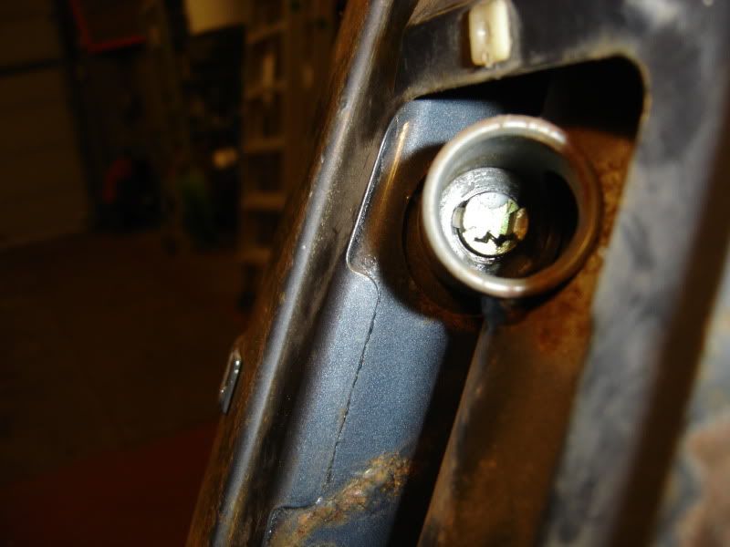
Het volgende gedeelte is waarschijnlijk een struikelblokje om er uit te krijgen. het detail om dit er uit tekrijgen ligt hem aan het lipje die je moet induwen. Hier onder op de foto zie je aan de linker kant van het centerstuk een lipje zitten. Die duw je naar het midden toe en trek je ondertussen het sleutel-cilinderslot uit zijn zitting.

The next part is probably a stumbling block to get out. The detail on how to get this out is the tab that you have to push in. The picture below you see on the left side of the center piece a white tab. Push that towards the center and pull in the meantime the key cylinder from its housing.


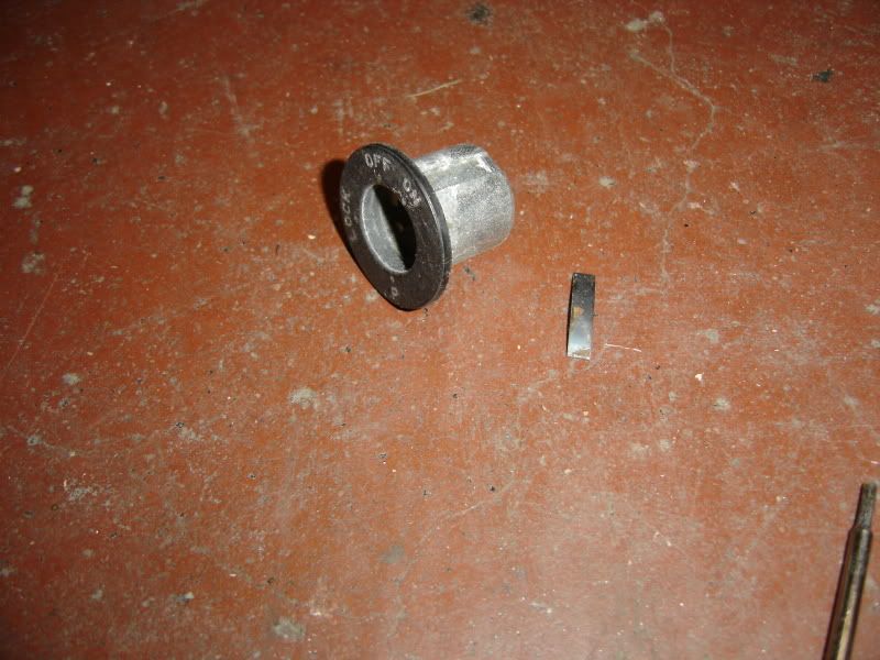
Wanneer je dit juist heb zou je dit moeten over hebben.

If you did this correct, you will have this left over.
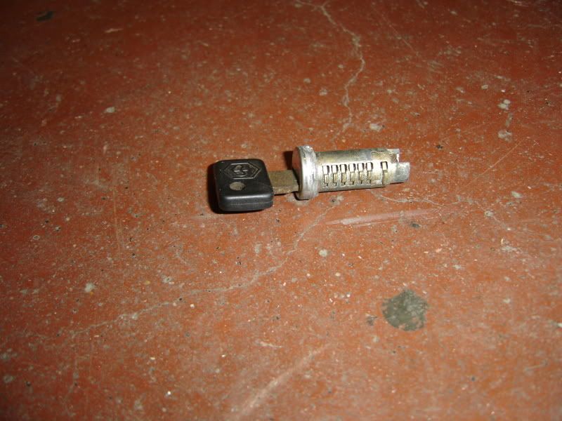

en dit...

and this...


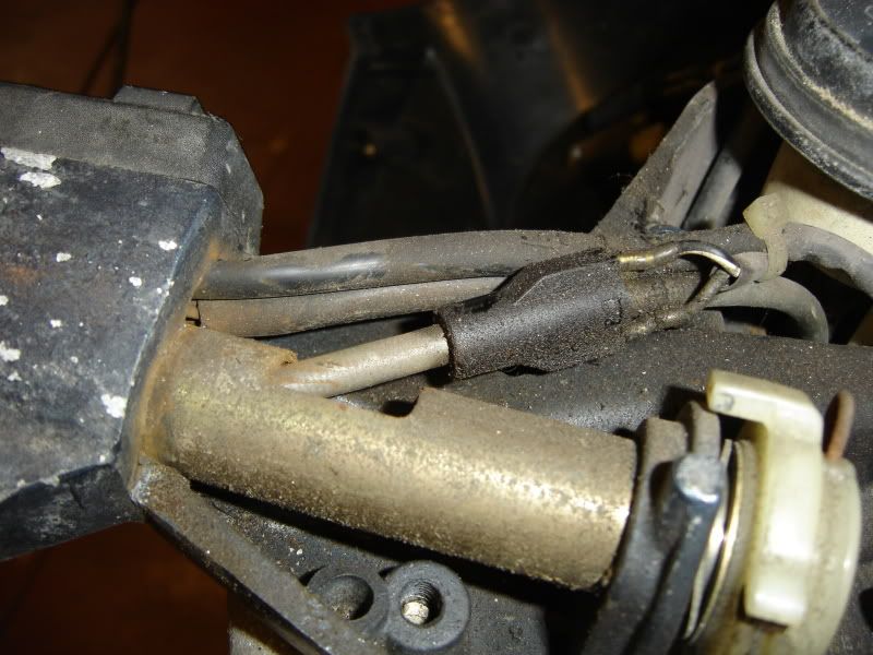
Het laatste stuk moet je voorzichtig met een fijne schroevendraaier er uit schuiven. Let op de stalen "bladveertje" die de hele zaak op zijn plaats moet houden.

Ik hoop met deze je toch heel wat prutswerk bespaard te hebben.

The last part you should carefully slide out with a fine screwdriver. Note the steel "leaf spring" that keeps the whole thing in place.

I hope to have saved you a lot of misery with this…


zaterdag 15 oktober 2011

Demonteren van het chassis. - Disassembly of the chassis.

Donderdag ben ik in beperkte mate kunnen beginnen met het demonteren van het chassis. Beperkt..., voor de mensen die weten wat ik doe, 5 oproepen in de loop van de avond. Dus het woord beperkt is niet overdreven. Maar toch ben ik kunnen beginnen en dat was voor mij terug een stap vooruit in het reviseren van de Vespa in het geheel.
Het leek mij het meest logische te beginnen met de stuurkap gezien dit het verzamelpunt is van alle trekkabels voor rem, koppeling en versnellingen. Het biedt na verwijderen ook wat meer plaats om de elektrische bekabeling, die via de stuurkolom naar boven loopt vanuit de verzamelstekker vooraan de stuurkolom, er uit te schuiven.


Thursday I am limited to begin disassembling the chassis. ... Limited, for the people who know what I do, 5 calls during the evening. So I don’t exaggerate with the word . But still, I could start and that was for me a step forward in the revision of the Vespa as a whole.
It seemed most logical to start with the handlebars, this being the assembly point  of all the tension cables for brake, clutch and gears. It also offers more space, after removing these, for the electrical wiring that runs through the steering column upward from the front of the steering column assembly connector, to slide  out.


Zonder stuurkap. Dit moet je ook verwijderen wanneer je de lampen moet vervangen. 4 schroeven, 2 vooraan en 2 achteraan.


Without casing. You must also remove this when you need to replace the lamps. 4 screws, 2 at the front and 2 rear.


Je ziet ook hoe de trekkabels door de kap verdwijnen en vervolgens  in de buitenmantel van de kabels naar hun doel lopen. De trekkabels worden bevestigd in de witte plastiek geleiders die vast gemaakt worden met een pen door de holle as van de handvaten.
Hieronder zie je het contact op de remkabel voor de voorste rem. Met dit contact gaat uw achterlicht branden bij het remmen.


Here you see how the cables disappear through the casing into the outer jacket of the cables that run to their destination. The cables are fixed to the handlebars on the white plastic guides that are again fixed to the handlebar hollow shaft with a pin. Below you see the front brake contact.


Alle elektrische bekabeling komt samen vooraan de stuurkolom en wordt hier gekoppeld. Het is ten zeerste aangeraden dit allemaal te noteren voor men deze gaat verwijderen. Volg gewoon de kabels naar de stuurkap en je ziet direct waarvoor ze dienen.

All electrical wiring meets in the front of the steering column and is linked here. It is strongly recommended to make notes before we remove it. Just follow the cables to the handlebar and see immediately what they are used for.


Op de foto hieronder zie je welk type fiches het zijn die gekoppeld worden. Bovenaan de foto zie je het sleutelcontact die eveneens aan het verzamelpunt wordt aangesloten.

The picture below shows what type of contacts are linked. The top picture shows the contact key which also is connected to the assembly.


De voorrem en snelheidsmeter kabel wordt hier verwijderd. 

Here you can disassemble the front brake cable and speed cable.


Hopelijk kan ik hier volgende week terug verder aan werken met wat meer uitleg erbij.

Hopefully next week I can do some more work on this with some explanation with it.


maandag 3 oktober 2011

Revisie motor beëindigd. Overhaul of the engine complete.

Het reviseren van de motor is volbracht. Vorige week is er wat verder gedaan aan het terug monteren van alle stukken aan de motor. De 133cc kit van DR werd gemonteerd en de ontsteking terug aangesloten. Vorig weekend heb ik enkel de carburator volledig gereviseerd en een 80 sproeier gemonteerd ipv de 76 standaard.


The overhaul of the engine is complete. Last week  a bit more was done with reinstalling all the pieces to the engine. The 133cc DR kit was mounted and to the ignition connected. Last weekend I  completely overhauled the carburetor and mounted a 80 nozzle instead of the standard 76.


Als eerste keer moest er twee maal op de kickstarter getrapt worden zodat de benzine door de carburator kon vloeien om zo de cilinder te vullen met benzine mengsel. Met de tweede trap werd ze al opgestart.
Hieronder een kleine opname van het gebeuren.

For the first time she had to be kicked twice so the gasoline could flow through the carburetor into the cylinder and fill up with the gasoline mixture. The second kick, she was launched.
Below a small recording of the event.


Deze week of volgende week is de start van de revisie van het frame gedeelte.

This week or the next is the beginning of the overhaul of the frame part.

Stay tuned folks!